
¶ Introduction
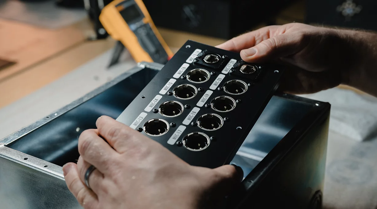
Catalyst is Venueflex’s solution to allow systems integrators to rapidly install high-quality, dependable audio and lighting control cabling using standard structured wiring systems. Instead of specialty AV cables, Catalyst exploits shielded Cat-5 and Cat-6 cabling for analog audio and digital connections, allowing rapid installation, termination, and testing.
In addition to labor savings, Catalyst exceeds the bandwidth performance of standard audio cabling systems. Long distance runs and studio-grade connections are possible with a fraction of the conduit fill and difficulty of conventional methods. Grounding, shielding and electrical isolation has been carefully engineered to make quiet, high-performance systems possible with minimal effort.
- Huge savings in termination labor
- Space-saving cable paths
- Noise-free connectivity
- Freedom from grounding and isolation issues
- Extended bandwidth over distance as compared with conventional audio cabling
- Easy system verification and testing
¶ Safety & Regulatory
¶ Important safety instructions
- Read these instructions.
- Keep these instructions.
- Heed all warnings.
- Follow all instructions.
- Do not use this equipment or components near water.
- Clean only with a dry cloth.
- Install in accordance with the manufacturer’s instructions.
- Do not install near any heat sources such as radiators, heat registers, stoves, or other apparatus that produce heat.
- Use only with the accessories specified by the manufacturer, or sold with the apparatus.
The Catalyst components and the Catalyst System are low-voltage, signal-level components. Ensure that proper and safe separation is maintained between low-voltage systems and any line voltages, and that grounding and bonding of low-voltage systems complies with all necessary codes and regulations.
It is the responsibility of the purchaser to verify that all work is completed in a safe manner, and compliant with any codes or regulations governing the installation.
¶ Catalyst Configurator

Click here to access the Catalyst Configurator through the Venueflex Portal.
The Venueflex Customer Portal contains the ability to create custom projects containing Catalyst plate systems. Using this tool, a user may easily and quickly lay out all plates, add modules, custom labeling and graphics to the design. Designs may then be instantly priced and issued for manufacture, allowing you to receive a fully-configured and assembled Catalyst system.
Venueflex strongly encourages customers to use the Catalyst Configurator to create their Catalyst system designs. This helps ensure you receive the most accurate product possible with minimal effort.
¶ Using Catalyst
A Catalyst wiring system is composed of two major components, plates sized for wall, floor or rack mount enclosures, and modules that populate those plates to provide connectivity between Category cabling and other AVL equipment. Catalyst may be installed using shielded CAT-5 or CAT-6 category cabling and conventional shielded RJ45 connectors. The entire product range is fully modular, and easily assembled by the dealer for fast specification, installation and customization.
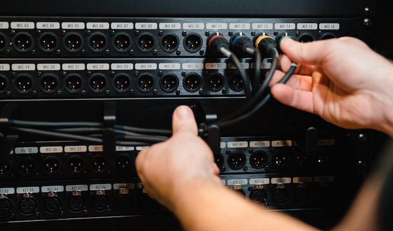
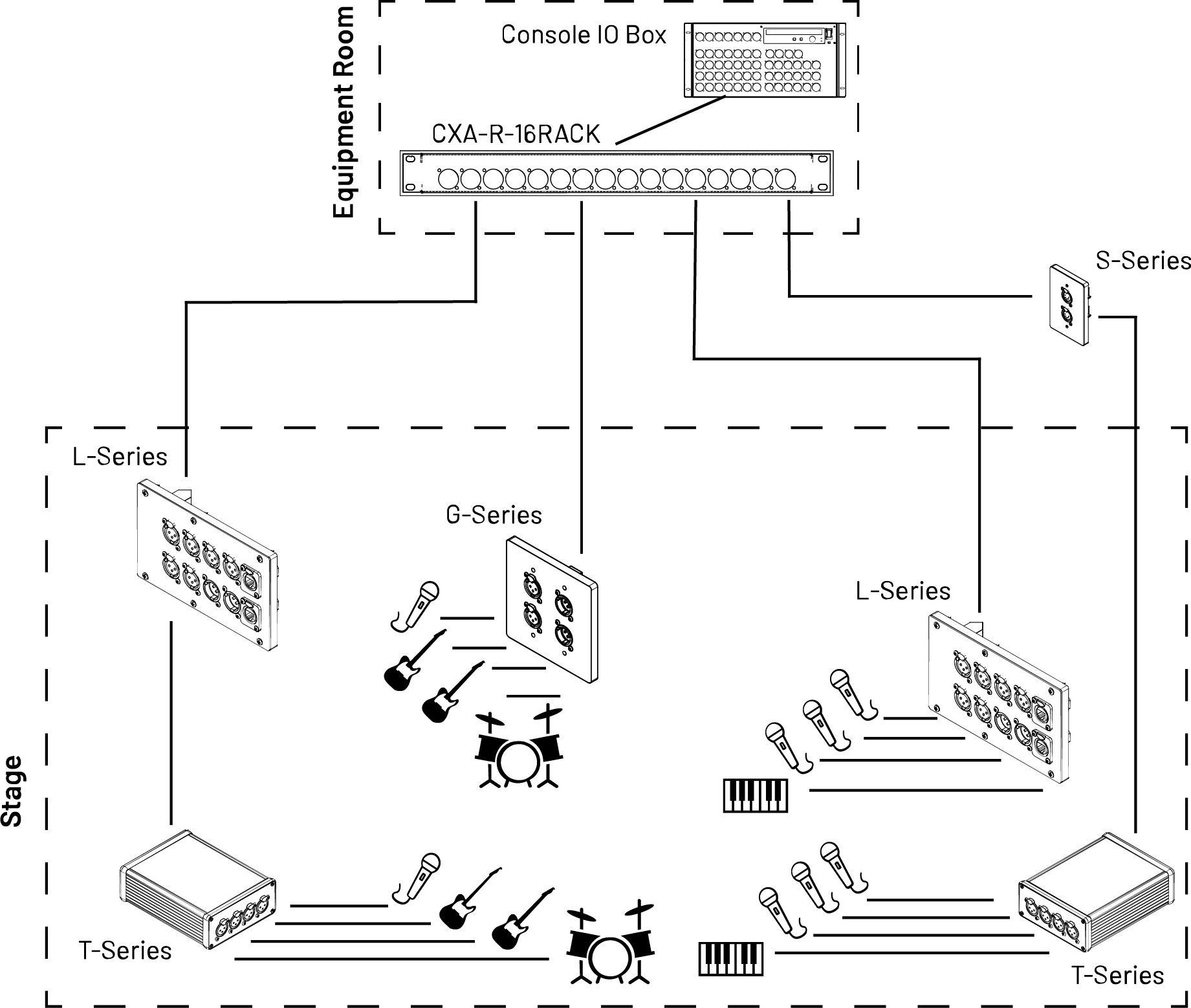
A typical example for a production-oriented Catalyst install is shown in the figure below. In this case, a rack-mounted panel (R-Series) provides patching into an adjacent audio IO box. Installed category cabling extends from the rack out to endpoints throughout the building, with floor and wall boxes populated using Catalyst plates and modules (in this case, L-Series and G-Series). Sub-snakes are then used throughout the stage for additional flexible IO, using the T-Series touring portable boxes. Endless combinations are possible using variations of this scheme, and wiring issues and cable size is minimized.
For audio signal transport, Catalyst uses the AES 72 wiring standard. This means each Category cable supports four balanced audio pairs, meaning four analog channels or four pairs (8 channels) of AES3 digital audio per cable.
Catalyst audio channels are labeled A B C D. This allows you to track which physical connector connects through on each end of a Catalyst link.
¶ Catalyst modules
Catalyst modules are purpose-built for specific plate and box scenarios to help you integrate Catalyst into nearly any AV environment. Catalyst modules may be broken down into various "series" depending on their physical design and intended application, as shown below:
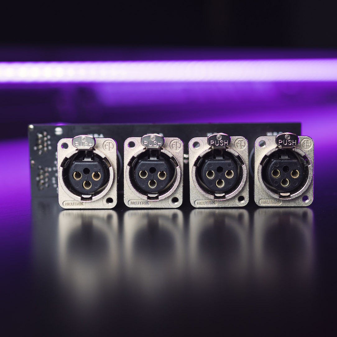 |
L-Series: "Linear" series, for high-density floor and wall box applications. Compatible with L-Series plates. |
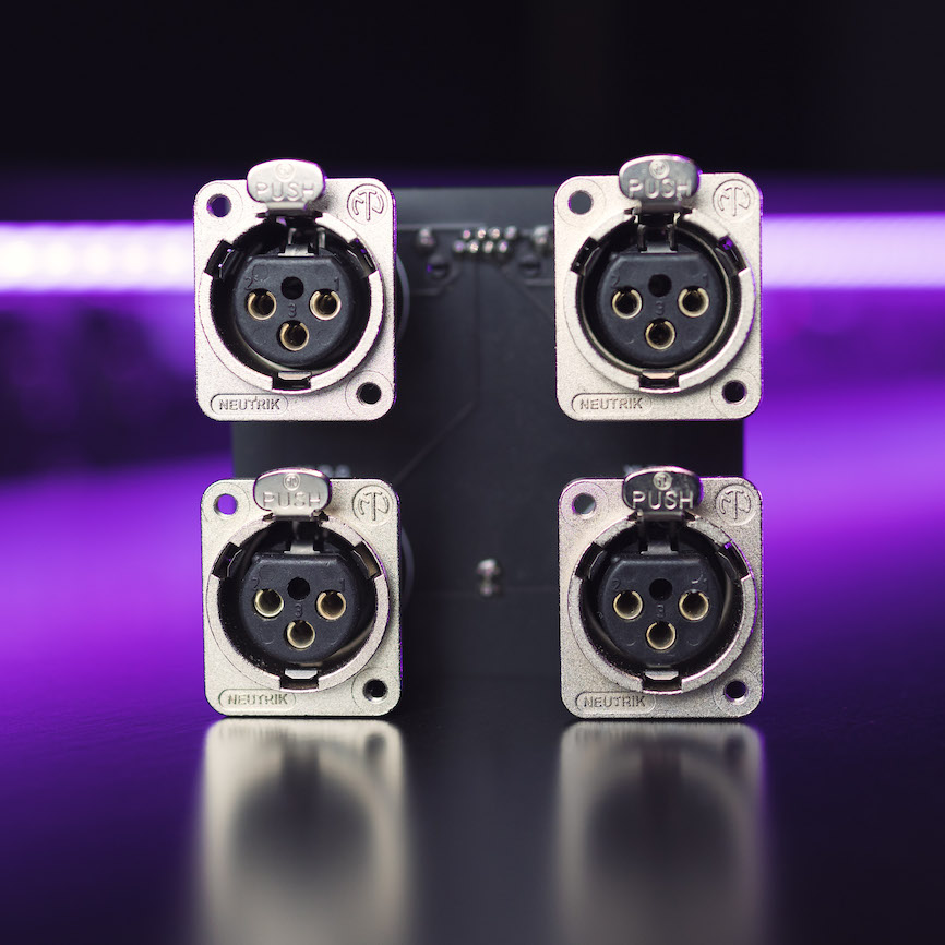 |
G-Series: "Gang" series, for NEMA-sized floor and wall boxes. Compatible with G-Series plates. G-Series are numbered from top to bottom not left to right like the rest of the modules. So input 1 is top left and input 2 is bottom left. |
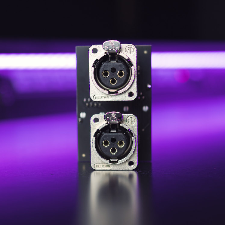 |
GS-Series: "Gang-Switchable" series, for NEMA-sized floor and wall boxes with switchable channel assignments for each connector. Compatible with G- and S-Series plates. |
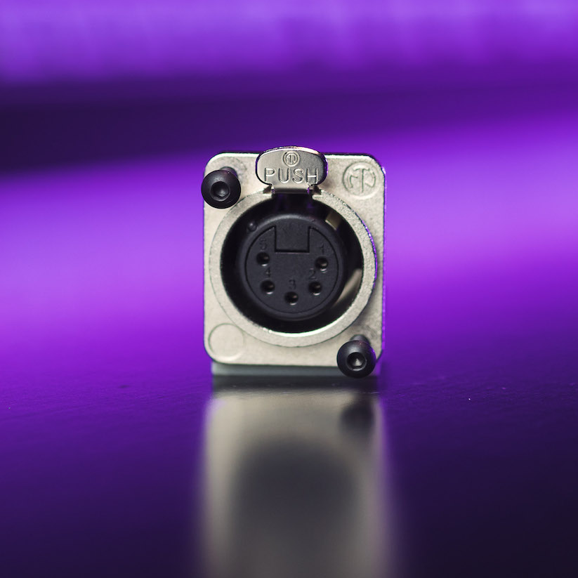 |
S-Series: "Single" series, standard "D"-mount geometry. Compatible with L-, G- or S-Series plates. |
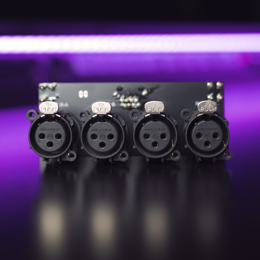 |
R-Series: "Rack" series, Can be used in a standard 19-inch equipment rack. Compatible wth R-Series rack plates. |
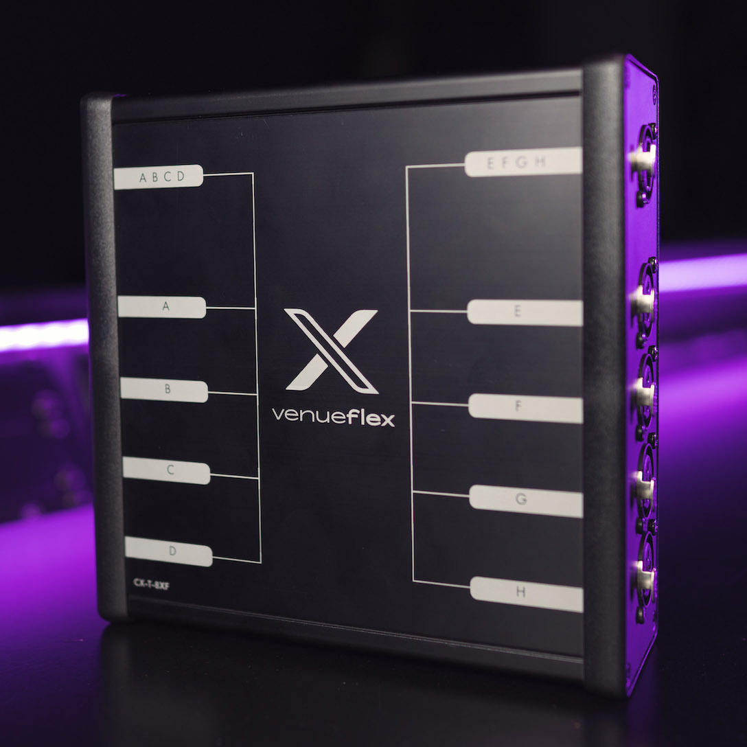 |
T-Series: "Touring" series, Can be used standalone, or as a subnake or break-out box for a larger system or stage installation. |
The table below breaks down which modules are available for various applications.
| Requirement | Back box type | Catalyst Module Series |
|---|---|---|
| Floor box | Ace Backstage | L-Series - GS-Series - S-Series |
| FSR | L-Series - G-Series - GS-Series - S-Series | |
| Wall box | FSR | L-Series - G-Series - GS-Series - S-Series |
| Hoffman | L-Series - S-Series | |
| Generic NEMA gang boxes | G-Series - GS-Series - S-Series | |
| Rack mount | 19 inch equipment rack | R-Series |
| Subsnake breakout / portable | Portable stage box | T-Series |
¶ Catalyst plates
Catalyst plates are available to support a wide variety of industry-standard back boxes, including floor, wall, or rackmount enclosures. Catalyst plates are manufactured using a non-conductive thermoplastic, promoting excellent signal isolation and ground integrity. Conventional or custom metallic plates may also be used, however the user should excercise caution in esuring proper grounding and isolation if a metallic plate is used.
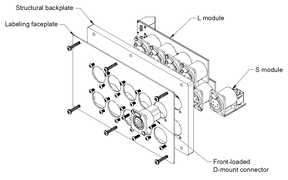
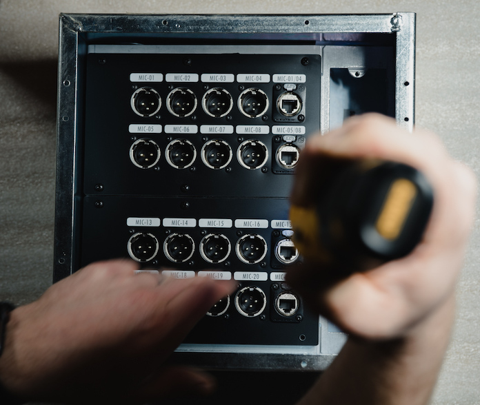
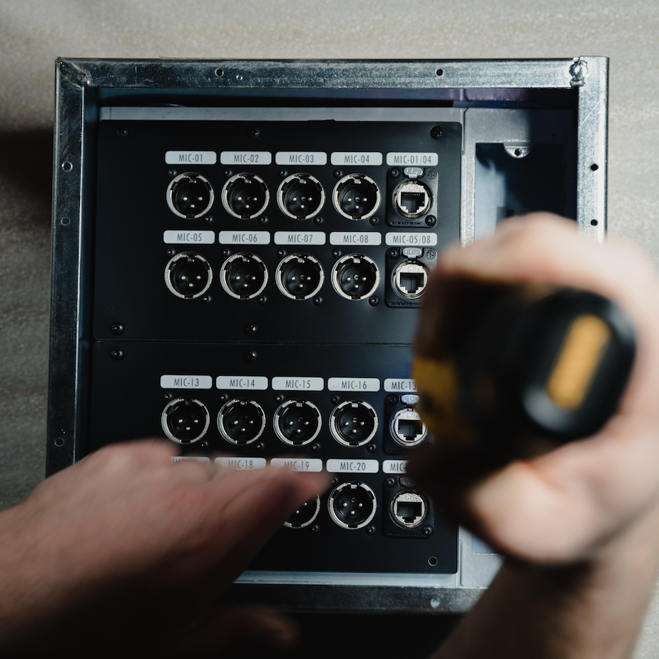
Catalyst plates are constructed from two layers, a base thermoplastic structural backplate plus a thin labeling faceplate. Complete plates are assembled by joining these layers with their appropriate modules and/or other compatible connectors. Fasteners are included with plates and modules for correct assembly. See the image above for a typical assembly.
Do not over-tighten any fasteners on plates! Damage to the connector or the labeling faceplate may occur. Always limit torque and hand-tighten all screws when assembling modules and when installing a plate in a backbox.
Catalyst labeling faceplaces may be custom laser-etched, either by Venueflex or by the reseller or end-user. In most cases, we recommend using the Catalyst Configurator to configure and label Catalyst plates.
¶ Catalyst cabling
¶ Installed premises cabling
The Catalyst system utilizes standard Category 5, 5e, 6, or 6A shielded cabling throughout. Standard shielded RJ45 connectors should be used on the input/output ports of the catalyst modules to connect to facility cabling. For best operation, respect the maximum signal distances shown in the table below.
Note: Due to lower total system capacitance, a typical Catalyst system significantly outperforms "standard" audio twisted pair cabling over distance in terms of bandwidth (high-frequency attenuation). This means that longer cabling distances are possible without negative signal degredation.
Some back boxes have limited clearance for devices and wiring. Use caution when terminating connectors for these boxes. Use care to avoid placing excessive mechanical stress on the connector or cable.
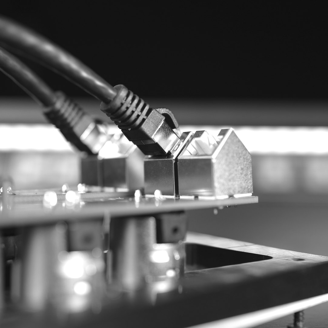
The figure above shows a typical termination behind a finished Catalyst plate. Ensure good cable management to provide:
- Minimum stress on the cable and connector when installed in the back box.
- An acceptable service loop.
- Avoid shorting the shell of the RJ45 to the box! This can create issues with electrical isolation and ground integrity.
Note, always use cabling appropriately rated for applicable local codes.
¶ Portable cabling
Venueflex recommends tactical-grade Category cabling for portable and touring use with T-Series modules and sub-snake assemblies. Note that connectors supplied with Catalyst plates are compatible with standard shielded RJ45 connectors, or Neutrik CAT5e and CAT6A Ethercon cable end connectors only.
¶ Grounding and isolation
The grounding and shielding of Catalyst has been carefully engineered to make installing a noise-free system easy and repeatable. Ground management is described below for both floor and wall box connectivity, and associated rack-mounted patch systems.
While great detail is provided in this section describing the grounding options available for Catalyst, in most cases, the default configuration of Catalyst is sufficient and the best possible choice for a noise-free installation.
In other words, the use of Catalyst non-conductive plates and the default grounding configuration of modules typically produces the best signal integrity and noise isolation with no additional effort!
¶ Floor and wall box plates
For best operation, we recommend Catalyst plates for use with L, G, GS and S series Catalyst modules used in "remote" floor and wall boxes in a venue. Our Catalyst plates are constructed from a non-conductive thermoplastic. This allows for AV cabling to be fully ground-isolated from the chassis ground of a typical floor or wall box. Ground issues from electrical outlets, conductive conduit or other items are therefore fully eliminated.
- Modules ship with either a jumper or DIP switch marked Pin 1 to Chassis. When using non-conductive plates, we recommend shorting this connector, or turning the DIP switch to ON. This is the default configuration of the module at the time of shipment.
- If custom, conductive (metal) plates are used which are bonded to a grounded electrical system, we recommend removing the Pin 1 to Chassis jumper or turning the equivalent DIP switch to OFF. Note this will tie plate chassis ground to the XLR connector shell while leaving the "Pin 1" audio ground independently connected back to the source.
Plate type |
Pin 1 to Chassis Selector Settings L and G module |
GS module |
|---|---|---|
 |
 |
|
| Catalyst non-conductive plate | Jumper shorted (default) | Switch ON (default) |
| Grounded conductive metal plate | Jumper removed | Switch OFF |
¶ Rack mount plates
Catalyst rack-mount plates are designed to act as either endpoints throughout a facility, or, more commonly, as a centralized "patch" panel for terminating cables that originate at remote floor and wallbox plates. Catalyst rack-mount plates are made from anodized aluminum, and, by default, are electrically bonded to the rails of the rack they are installed in.
Similarly to floor and wall box plates, Venueflex ships rack mount plates with a grounding and shielding configuration that is optimal for most installations. By default, the Pin 1 to Chassis jumper on R-Series modules is removed, meaning the "Pin 1" audio ground is separated from the connector shell and plate ground. Grounds from remote connectors flow through the rack panel and to the endpoint device, without being bonded to the chassis/shell ground. This ensures best noise performance, eliminating noise paths to the rack chassis and other equipment.
For custom installations, you may elect to add a jumper to the Pin 1 to Chassis jumper on the rear of the module, bonding the audio ground to the chassis. This should be done with caution and intentionality due to the potential to introduce outside noise sources into the audio system.

As shown in the image above, we recommend the following:
- Leave the Pin 1 to Chassis jumpers removed, as is the default.
- Install the included grounding jumpers between adjacent rack modules.
- At the end of a chain of rack modules, connect one of the ground lugs to the rack chassis ground. The rack chassis should be bonded to a safety ground reference per local electrical codes.
Using this mechanism, the audio signal ground is isolated from the rack chassis, but the chassis and connector shells are still shielded and bonded to the rack as a whole.
¶ Catalyst components
¶ L-Series

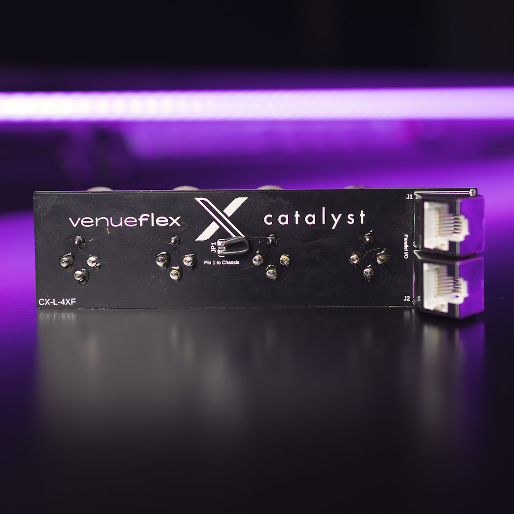
The Catalyst L-Series ("Linear") is intended for use in high-density Floor- and Wall-Box applications. Plate layouts are available for use with back boxes from Ace Backstage, FSR and Hoffman. Combine L-Series modules with S-Series modules or other D-Mount connectors for a complete plate and box design. The L-Series audio modules feature a pass-through for parallel connection to front-panel drop snake connections or to other modules in the system.
¶ Available modules
| Module | Connector gender 3-pin XLR |
Channel layout (connector view) |
|
|---|---|---|---|
| CX-L-4XF | F - F - F - F | A - B - C - D | |
| CX-L-4XM | M - M - M - M | A - B - C - D | |
| CX-L-2XF-2XM | F - F - M - M | A - B - C - D |
¶ Plate and box compatibility
L-Series plates are compatible with various industry-standard back boxes for easy integration into your systems. L-Series plates accept L-Series modules, S-Series (single) modules, and/or standard Neutrik D-mount connectors. Some clearance requirements apply. See below for compatibility:
| Catalyst Plate Number | Back box manufacturer | Compatible boxes | Notes | |
|---|---|---|---|---|
| CXA-L-10ACE | Ace Backstage | Double Wide, Super and Super Double Wide Stage Pockets | Fills one "120" sized plate slot. Accepts up to two L-Series modules plus additional connectors. | |
| CXA-L-10FSR | FSR | FL series | Fills one 4-gang plate slot. Holds up to two L-Series modules plus additional connectors. | |
| CXA-L-48-1212 | Hoffman | ASE12X12X4 or similar | Sized to match box dimension, for surface-mounted boxes (box mounted to wall surface). Accepts up to six L-Series modules plus additional connectors. | |
| CXA-L-48-1313 | Hoffman | ASE12X12X4 or similar | Oversized by 1 inch, for recessed-mounted boxes (box inside wall; plate flush to wall). Accepts up to six L-Series modules plus additional connectors. | |
| CXA-L-35-WFF1212 | Hoffman/Whirlwind | ASE12X12X6 (required for clearance) or similar with Whirlwind WFF12x1 trim frame. Use of boxes with less than 6 inches of depth may require shims on plate or box. | Accepts up to five L-Series modules plus additional connectors. |
¶ Pass-through capability
A popular and convenient feature of the L-Series modules are their integrated RJ45 passthrough connectors. By plugging into the second connector on the module, a complete, parallel connection may be made to the incoming signal(s) and the module connectors. This can be used to either extend mirrored audio to other connections in the system, or to bring a copy of that audio to a front-panel Neutrik jack for use as a "subsnake" output. In this way, the four audio pairs available on the module are also available for plugging portable cabling into a plate, allowing the use of T-Series subnakes on a stage. The subsnake will then be connected in parallel to the L-Series module.
Catalyst module CX-S-1E consists of a jumper cable plus a front-panel CAT6a Ethercon passthrough jack. This part number plus the "fifth" hole on an L-Series plate allows for a subsnake connection to any L-Series module.
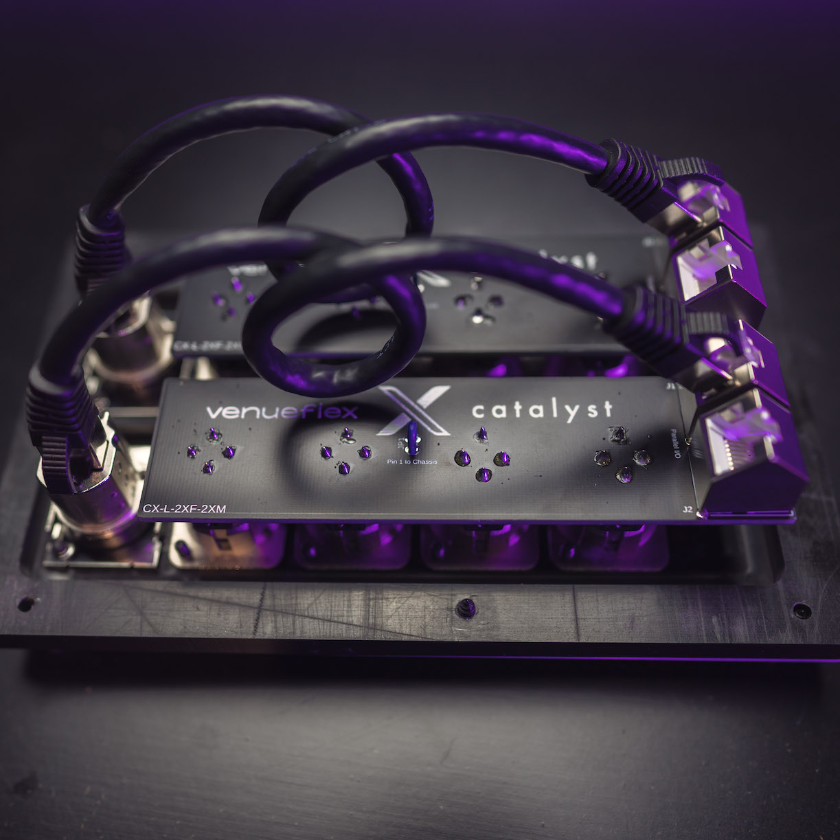

(Right) L-Series floor box plates with integrated subsnake connections.
¶ G-Series

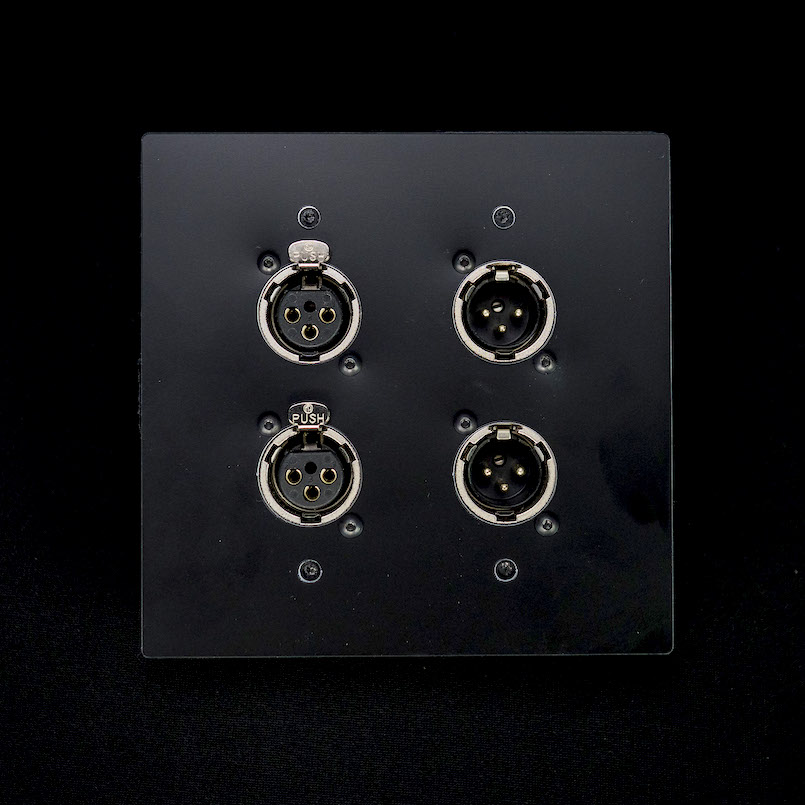
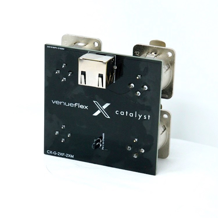
The Catalyst G-Series ("Gang") is intended for use in standard NEMA gang boxes, and other NEMA-sized specialty boxes, such as those from FSR. Note that, due to space limitations, there is not a secondary loop-through RJ45 on G-Series modules.
G-Series are numbered from top to bottom not left to right like the rest of the modules. So input 1 is top left and input 2 is bottom left.
¶ Available modules
| Module | Connector gender 3-pin XLR |
Channel layout (connector view) |
|
|---|---|---|---|
| CX-G-4XF | F - F F - F |
A - C B - D |
|
| CX-G-4XM | M - M M - M |
A - C B - D |
|
| CX-G-2XF-2XM | F - M F - M |
A - C B - D |
¶ Plate and box compatibility
G-Series plates are compatible with various industry-standard back boxes for easy integration into your systems. G-Series plates accept G-Series modules, GS-Series modules, S-Series (single) modules, and/or standard Neutrik D-mount connectors. Some clearance requirements apply. See below for compatibility:
| Catalyst Plate Number | Back box manufacturer | Compatible boxes | Notes | |
|---|---|---|---|---|
| CXA-G-4WALL | Generic | NEMA double-gang box | Min 3" depth. Accepts one G-Series module or up to two GS-Series modules or additional connectors. | |
| CXA-G-4FSR | FSR | FL series | Fills one 2-gang plate slot. Accepts one G-Series module or up to two GS-Series modules or additional connectors. | |
| CXA-G-8FSR | FSR | FL series | Fills one 4-gang plate slot. Accepts up to two G-Series modules or up to four GS-Series modules or additional connectors. |
¶ GS-Series

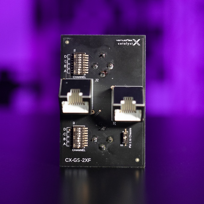
The Catalyst GS-Series ("Gang Switchable") is intended for use in standard NEMA gang boxes, and other NEMA-sized specialty boxes, such as those from FSR. Each terminating connector may be individually assigned to a Catalyst audio channel at will using a simple DIP switch, allowing fully-custom channel and connector arrangements. The GS-Series audio modules feature a pass-through for parallel connection to front-panel drop snake connections or to other modules in the system.
¶ Available modules
| Module | Connector gender 3-pin XLR |
Channel layout (connector view) |
|
|---|---|---|---|
| CX-G-2XF | F F |
Assignable Assignable |
|
| CX-G-2XM | M M |
Assignable Assignable |
|
| CX-G-1XF-1XM | F M |
Assignable Assignable |
¶ Plate and box compatibility
Catalyst plates are compatible with various industry-standard back boxes for easy integration into your systems. GS-Series modules fit into G-Series and S-Series plates. Some clearance requirements apply. See below for compatibility:
| Catalyst Plate Number | Back box manufacturer | Compatible boxes | Notes | |
|---|---|---|---|---|
| CXA-G-4WALL | Generic | NEMA double-gang box | Min 3" depth. Accepts one G-Series module or up to two GS-Series modules or additional connectors. | |
| CXA-G-4FSR | FSR | FL series | Fills one 2-gang plate slot. Accepts one G-Series module or up to two GS-Series modules or additional connectors. | |
| CXA-G-8FSR | FSR | FL series | Fills one 4-gang plate slot. Accepts up to two G-Series modules or up to four GS-Series modules or additional connectors. | |
| CXA-S-2WALL | Generic | NEMA single-gang box | Min 3" depth. Accepts one GS-Series module or additional connectors. | |
| CXA-S-2ACE | Ace Backstage | Stage pocket | Fills one single-gang plate slot. Accepts one GS-Series module or additional connectors. | |
| CXA-S-2FSR | FSR | FL series | Fills one single-gang plate slot. Accepts one GS-Series module or additional connectors. |
¶ Channel assignments
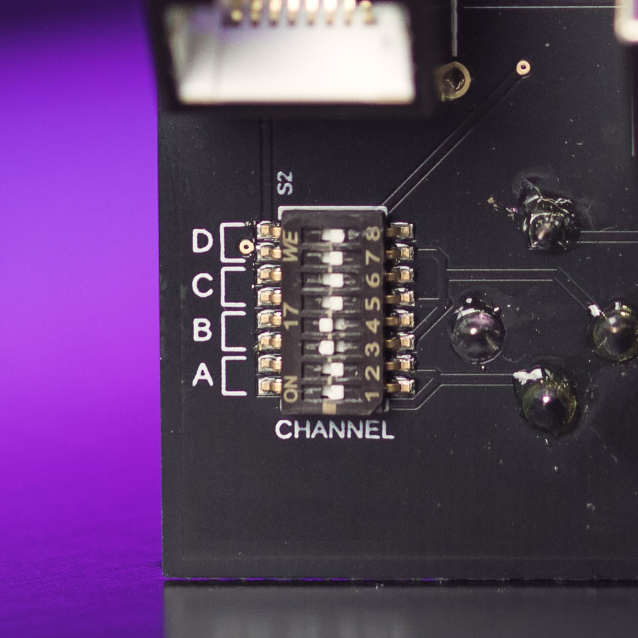
Each of the two connectors on a GS-Series module is individually assignable to any one of the four incoming Catalyst audio pairs (A, B, C or D). This can be used to create any number of convenient connector arrangements. Each connector may be assigned to any channel, no channel, or even the same channel! This provides the ability to create universal connections, mirrored connections, or the simple ability of distributing multiple audio channels around a room with one cable.
Behind each connector is a small DIP switch. To assign a channel to that connector, simply move both switches labeled with the desired channel name to the ON position, and ensure all other channel switches are set to OFF. See below for an example.
¶ Pass-through capability
A convenient feature of the GS-Series modules are their integrated RJ45 passthrough connectors. By plugging into the second connector on the module, a complete, parallel connection may be made to the incoming signal(s). This can be used to either extend mirrored audio to other connections in the system, or to bring a copy of that audio to a front-panel Neutrik jack for use as a "subsnake" output. This method also allows the daisy-chain connection of multiple GS modules in distribution applications.
¶ S-Series
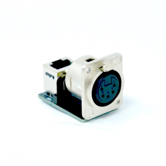
The Catalyst S-Series complements our L- and G- series plate systems to provide additional connectivity beyond audio pairs. Single RJ45 modules can provide multipair pass-through for any audio pairs, either looping from L-series modules or additional remote lines, four pairs at a time. In addition, include ANSI standard DMX512 connections over the same category cabling.
¶ Available modules
| Module | Description | |
|---|---|---|
| CX-S-1DF | Single female 5 pin XLR - ANSI DMX512 standard wiring to RJ45 on back panel. | |
| CX-S-1E | Single female CAT6a Ethercon including shielded link cable for drop snake connection with other modules. | |
| CXA-S-BLANK | Single D-Mount blank, for covering unused but cut ports in Catalyst plates. |
¶ Plate and box compatibility
Catalyst plates are compatible with various industry-standard back boxes for easy integration into your systems. S-Series modules fit into all L-Series, G-Series and S-Series plates as a standard D-Mount connector. Some clearance requirements apply. See below for specific S-Series plates:
| Catalyst Plate Number | Back box manufacturer | Compatible boxes | Notes | |
|---|---|---|---|---|
| CXA-S-2WALL | Generic | NEMA single-gang box | Min 3" depth. Accepts up to two D-mount connectors. | |
| CXA-S-2ACE | Ace Backstage | Stage pocket | Fills one single-gang plate slot. Accepts up to two D-mount connectors. | |
| CXA-S-2FSR | FSR | FL series | Fills one single-gang plate slot. Accepts up to two D-mount connectors. |
¶ R-Series

The R-Series forms the core of a typical Catalyst system, allowing home runs from remote IO plates to be centrally terminated and patched in an equipment rack. Each remote plate can connect to a complementary rack module, which may then be patched with standard XLR patch cables into local equipment.
Note the R-Series is constructed from high-density Neutrik A-Mount connectors. D-Mount connectors or other Catalyst modules will not fit into the R-Series rack mount plate.
¶ Available modules
| Module | Connector gender 3-pin XLR |
Channel layout (connector view) |
|
|---|---|---|---|
| CX-R-4XF | F - F - F - F | A - B - C - D | |
| CX-R-4XM | M - M - M - M | A - B - C - D | |
| CX-R-2XM-2XF | M - M - F - F(1) | A - B - C - D |
(1)Note that gender of the CX-R-2XM-2XF is opposite of the complementary L- and G- modules, allowing and end-to-end connection with proper gender on each side.
| Module | Description | |
|---|---|---|
| CXA-R-BLANK | Single A-Mount blank, for covering unused ports in Catalyst rack plates. |
¶ Plate and box compatibility
Catalyst R-series plates are compatible with standard 19-inch equipment racks. See below for plate options:
| Catalyst Plate Number | Back box manufacturer | Compatible boxes | Notes | |
|---|---|---|---|---|
| CXA-R-16RACK | Generic | 19-inch equipment rack | Accepts up to four R-Series modules (16 audio pairs), with A-mount knockouts. |
¶ Wiring and grounding scheme
Please reference the provided grounding and isolation information for instructions on properly grounding R-Series modules installed inside an equipment rack.
¶ T-Series

T-Series stage breakout boxes allow for remote IO to be connected throughout a stage, using a single flexible category cable for each set of four audio pairs. Use the CX-T-4XF and -8XF models to extend microphone inputs to areas like drum or keyboard risers. The CX-T-4XFM can be used to extend output lines, or can be used in standalone pairs to move audio around in portable applications.
¶ Available modules
| Module | CAT5e/6a Ethercon I/O | 3-pin XLR I/O | |
|---|---|---|---|
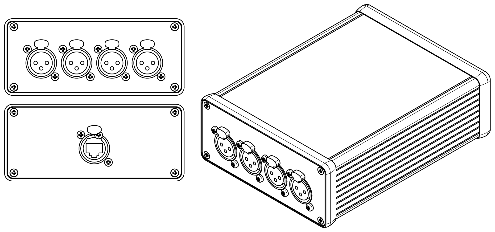 |
CX-T-4XF | One Ethercon (Four analog channels) |
Four female XLR |
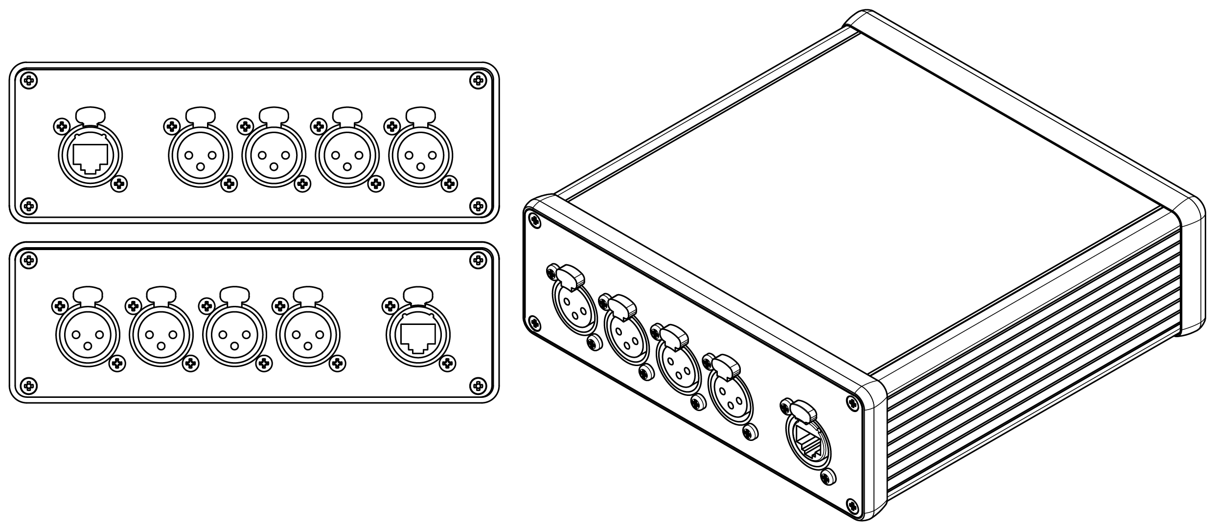 |
CX-T-8XF | Two Ethercon (Eight analog channels) |
Eight female XLR |
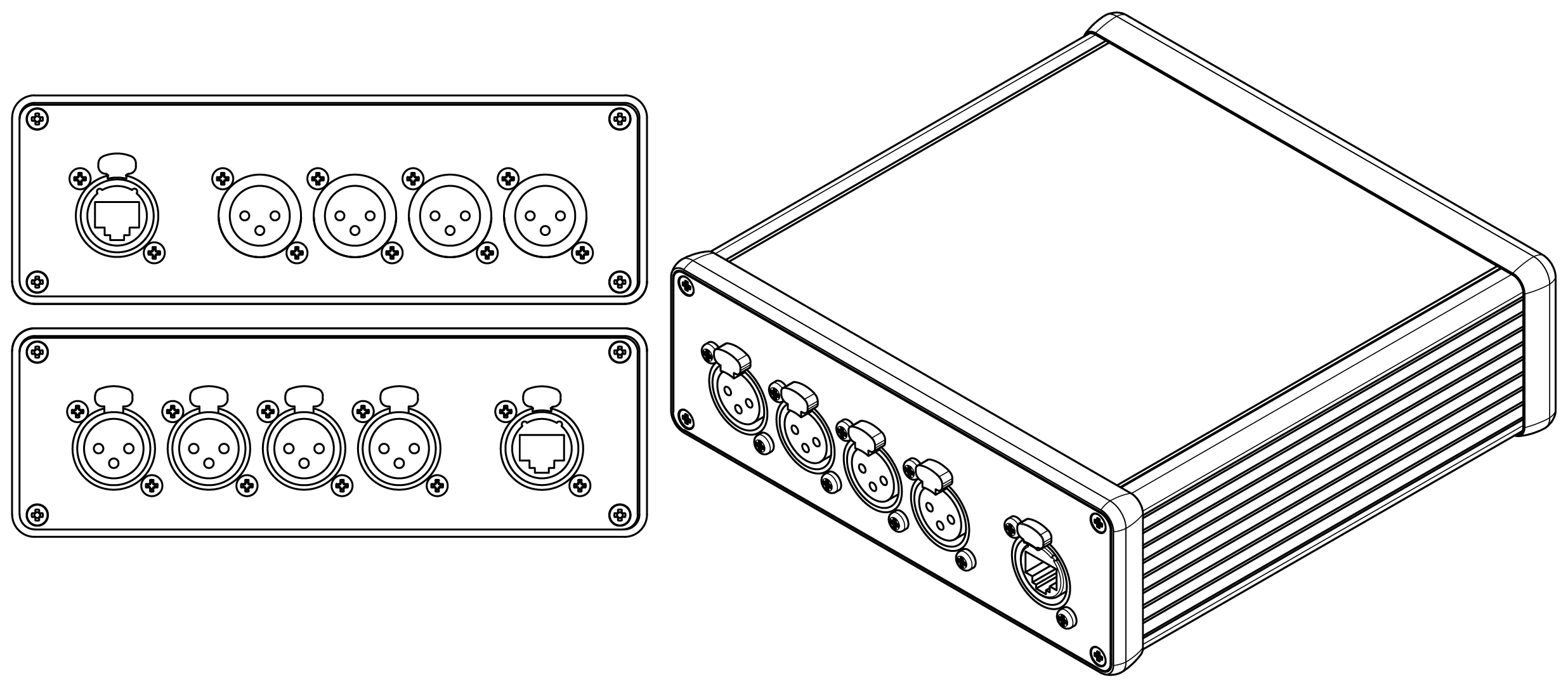 |
CX-R-4XFM | Two Ethercon in parallel for loop-through (Four analog channels) |
Four female XLR in parallel with four male XLR (universal connectivity) |
All modules are compatible with Neutrik Ethercon CAT5e/CAT6a cable connectors, and are compatible with all Catalyst modules for standalone or sub-snake applications. Venueflex recommends the use of tactical-grade flexible cable for on-stage or portable use.
¶ Downloads
¶ Plate drawings
| Module Number | Files |
|---|---|
| CXA-L-10ACE | PDF - DWG |
| CXA-L-10FSR | PDF - DWG |
| CXA-L-48-1212 | PDF - DWG |
| CXA-L-48-1313 | PDF - DWG |
| CXA-L-35-WFF1212 | PDF - DWG |
| CXA-G-4WALL | PDF - DWG |
| CXA-G-4FSR | PDF - DWG |
| CXA-G-8FSR | PDF - DWG |
| CXA-S-2WALL | PDF - DWG |
| CXA-S-2ACE | PDF - DWG |
| CXA-S-2FSR | PDF - DWG |
| CXA-R-16RACK | PDF - DWG |
¶ Specifications
¶ System specifications and standards
| Audio | Wiring topology | AES 72-2019 Type 1M |
| Maximum cable distance | Analog or AES 3-2009 digital audio to 400m (1300ft) | |
| Lighting | Wiring topology | ANSI E1.11 – 2008 (R2018) |
| Maximum cable distance | DMX512 data to 300m (1000ft) | |
| Cabling | Cabling type | ISO/IEC 11801 Category 5 or 6 Shielded |
| Connector type | Shielded IEC 60603-7-1 8-position modular connectors (Shielded RJ45) |
¶ Audio wiring scheme
Audio wiring scheme shown for four (4) balanced pairs, channels A, B, C and D. Compliant with AES 72-2019 Type 1M.
| RJ45 terminal | XLR pin | Signal name |
|---|---|---|
| SHIELD | (ALL) pin 1 | Audio ground, shared |
| 1 | A pin 2 | A+ |
| 2 | A pin 3 | A- |
| 3 | B pin 2 | B+ |
| 4 | C pin 2 | C+ |
| 5 | C pin 3 | C- |
| 6 | B pin 3 | B- |
| 7 | D pin 2 | D+ |
| 8 | D pin 3 | D- |
¶ Lighting (DMX512) wiring scheme
DMX512, compliant with ANSI E1.11 – 2008 (R2018).
| RJ45 terminal | XLR pin | Signal name |
|---|---|---|
| SHIELD | Pin 1 | Data link common |
| 1 | Pin 3 | Data 1+ |
| 2 | Pin 2 | Data 1- |
| 3 | Pin 5 | Data 2+ |
| 4 | No connection | |
| 5 | No connection | |
| 6 | Pin 4 | Data 2- |
| 7 | Pin 1 | Data link common |
| 8 | Pin 1 | Data link common |